RADAR SPEED SIGN – USER SETUP GUIDE
IMPORTANT MESSAGE
NOTE – No phone support is provided relating to setting up your Radar Speed Sign. The User Guide below explains how to setup your device. Ensure that you follow and perform ALL steps within the guide, and do not skip any steps. No phone support is provided for device setup. If you have any questions, do not call, instead send us an email explaining any issue in detail along with photos. We will provide the required support through email, and if we deem necessary, we will call you if the issue is NOT a human error.
STEP (1) – Account Registration & Hardware Activation
Click on the LINK (Register – Radar Speed Sign) below and follow the prompts to register a User Account, and/or, to Activate a Radar Speed Sign. Once you have submitted the form, you will receive an email within 1 to 24hrs confirming your User Account is registered, and/or, that your Radar Speed Sign is assigned to your User Account. You cannot proceed any further with setting up your Radar Speed Sign until you have received confirmation via email that your User Account is activated. Note – To Activate your Radar Speed Sign, you will require the “Bluetooth Name” as part of the registration process. The Bluetooth name can be obtained by powering on the Radar Speed Sign and viewing it on the LED Screen, noted as BLE.
STEP (2) – Install APP
Goto your Smartphone APP store and search & Install the Radar Speed Sign APP named “RADAR SIGN CONFIGURATOR”. The APP is available for both IOS and ANDROID.

STEP (3) – APP Login
Once you have installed the APP on your smartphone, login to the APP using the details submitted when registering your device in “STEP (1)”.
Your account details are used for both the User APP and to login to the Cloud CMS platform for remote monitoring of your Radar Speed Sign. The Cloud CMS will enable you to view the traffic data collected, deployment locations, timestamp of all captured events, and device parameters.
You can also assign multiple users to your devices, which allows them to view collected data via the Cloud CMS platform. All captured data is displayed in graphical analytics, with the option to download the raw data as a CSV file.

STEP (4) – Power On Hardware
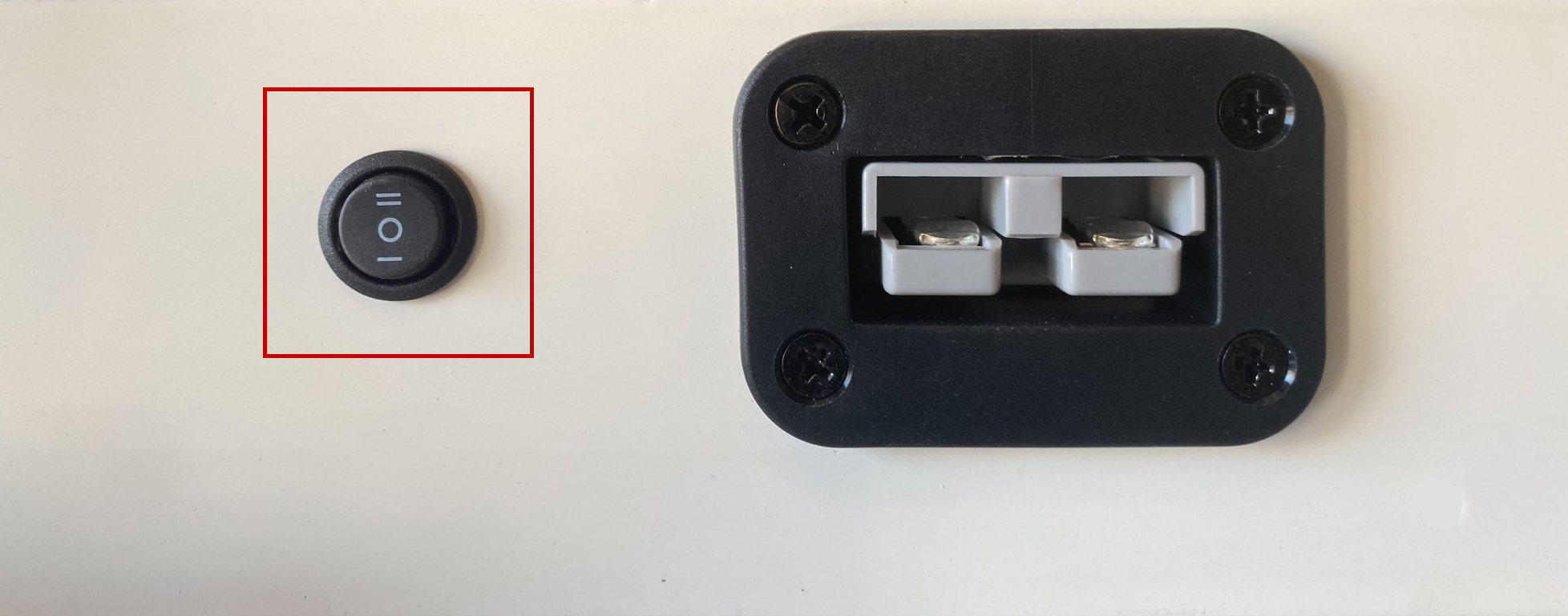
Next, power on the Radar Speed Sign by selecting the power switch to position (II). The power switch is located on the bottom side of the Radar Speed Sign. Note that position (I) is for charging the internal battery. When the switch is in position (I), the Radar Speed Sign will not power on, as it is in charging mode.
STEP (5) – Startup Status
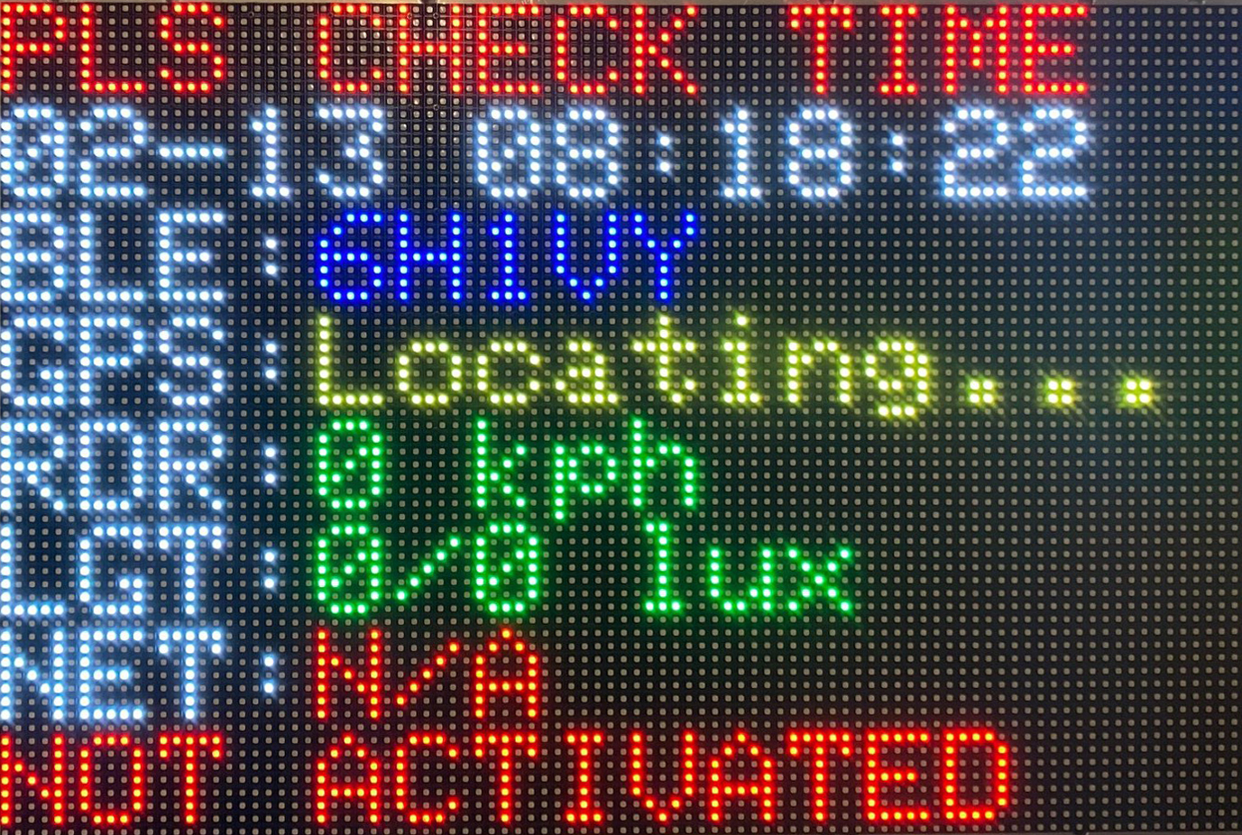
When powered on, the Radar Speed Sign will display a start-up screen, which will remain for approx 60secs until the software initialises for the first time as a “Not Activated” device.
Once initialised, the screen will display the status of the Radar Speed Sign hardware (right image), such as Date/Time, (BLE) Bluetooth Name, (GPS) GPS Status, (RDR) Radar Status, (LGT) Light Sensor Status, (NET) Network Status, and Activation Status if not activated. All items should be displayed in the same colours as the referring image to the right. The “NOT ACTIVATED” message on the last line, means that this device has not been activated and a “Serial Code” is required.
STEP (6) – Connect to Hardware
Ensure that your smartphones Bluetooth is enabled, if it is disabled, you will be prompted to enable Bluetooth in the APP so that your smartphone can connect to your Radar Speed Sign.
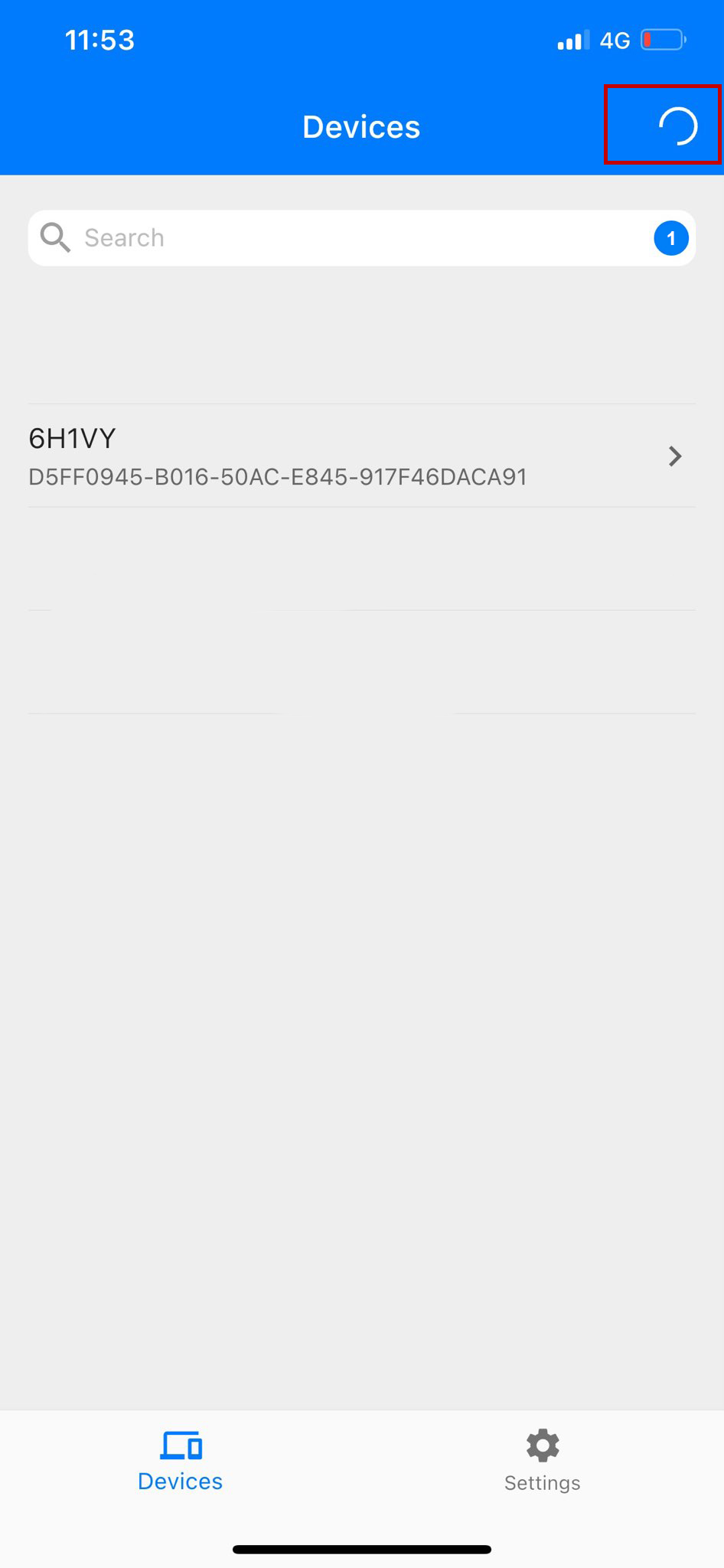
Press the search icon in the top right-hand corner of the APP “Devices” page, and select the Bluetooth name from the list of found devices that corresponds with the “BLE” name displayed on your Radar Speed Sign screen. Once selected, your Smartphone will be connected to the Radar Speed Sign.
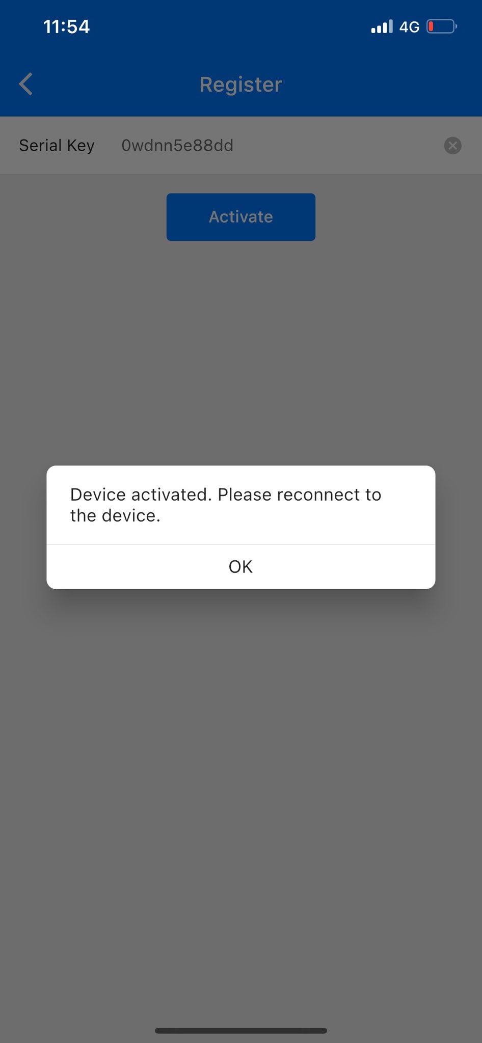
Now that your smartphone is connected to the Radar Speed Sign, you will be prompted to enter the emailed “Serial Key”. Upon pressing “Activate”, you will receive a notice stating that your device is activated. Disconnect the connection by logging out of the APP, than log back in to complete the hardware activation process.
Device Activation Status
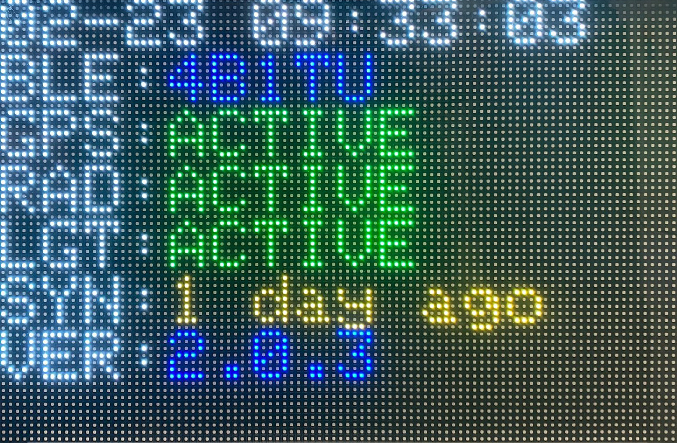
When your Radar Sign has been successfully activated, the start-up screen will display like the image to the right every time your Radar Speed Sign is powered on. This screen status will only display for 10 secs, than the Radar Sign will start “operation mode”.
Operation Mode is when the Radar Speed Sign is ready to detect traffic and display detected vehicle speeds on the Radar Speed Sign screen. Note that the Radar Sign screen will go “black” after displaying the “start-up status” info, and will remain “black” unless a vehicle is detected, in which that vehicles speed will then be displayed on the Radar Sign screen.
STEP (7) – Configure Device WIFI
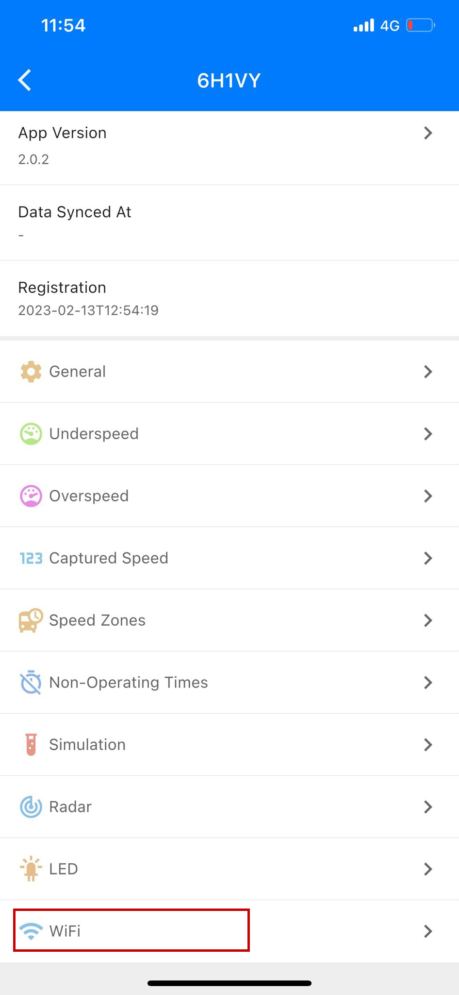
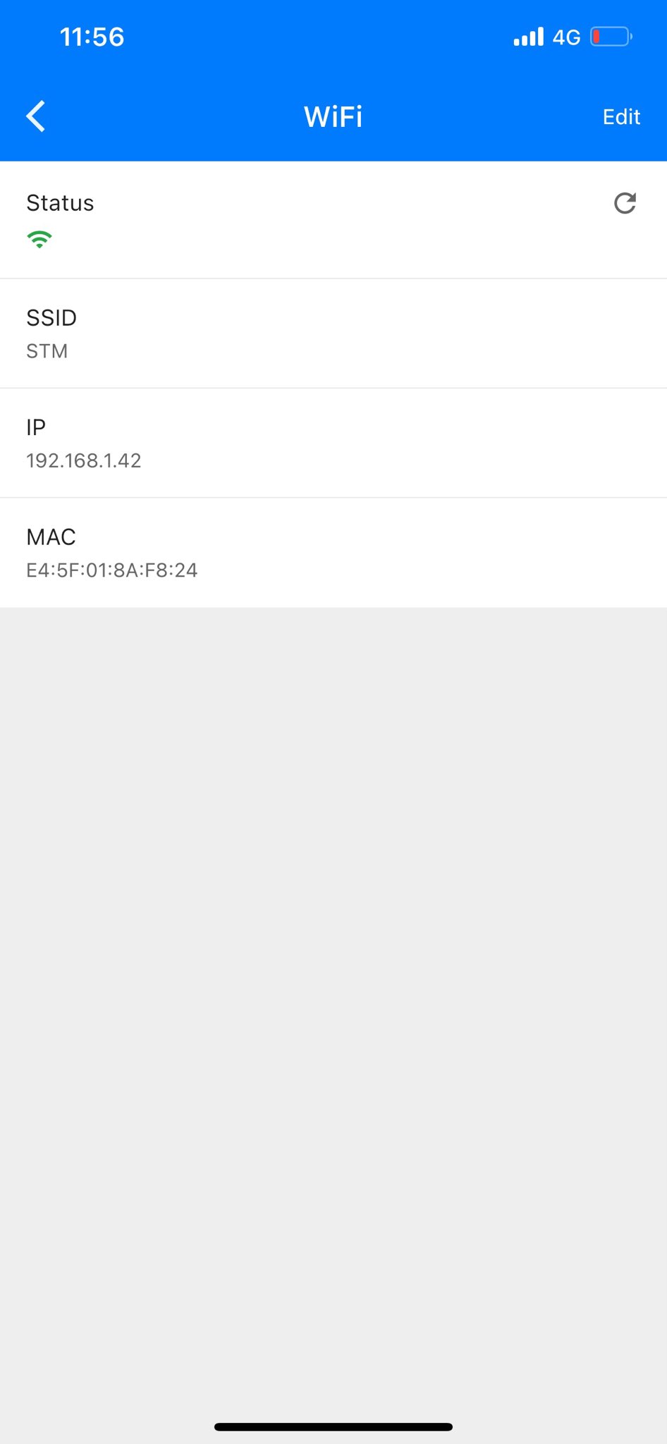
After logging back into the APP, go to the main menu and click on “WIFI”. Here you will need to enter a WIFI connection for your Radar Speed Sign, so that it is able to communicate to your Cloud CMS account for data collection upload/device updates/configuration. The best WIFI connection to use is the WIFI Hotspot generated by your smartphone.
Enter the WIFI SSID name (case sensitive) and password of your WIFI Hotspot, and press save; now power off for 10 secs; than power back on. Your Radar Speed Sign should now be connected to your WIFI Hotspot. To check your connection, go to “WIFI” menu on the APP and check that an IP has been allocated to your Radar Speed Sign. If there is no IP number, than your device is not connected. The Radar Speed Sign syncs collected traffic data with your Cloud CMS account on startup, and then every 9 minutes while your Radar Speed Sign continues to have a WIFI connection.
Note – The Radar Speed Sign does not require a continuous WIFI connection to operate. A WIFI connection is only required to sync the collected traffic data from your Radar Speed Sign to your Cloud CMS account for viewing.
STEP (8) – Configure Time Zone
Time Zone is an important feature of the Radar Speed Sign, each captured traffic event is time stamped, providing the user with valuable and accurate traffic analytics of events.
Once your time zone has been set, the built-in RTC (real time clock) will accurately keep time even when the Radar Speed Sign is powered off, allowing for quick deployment with accurate data collection.
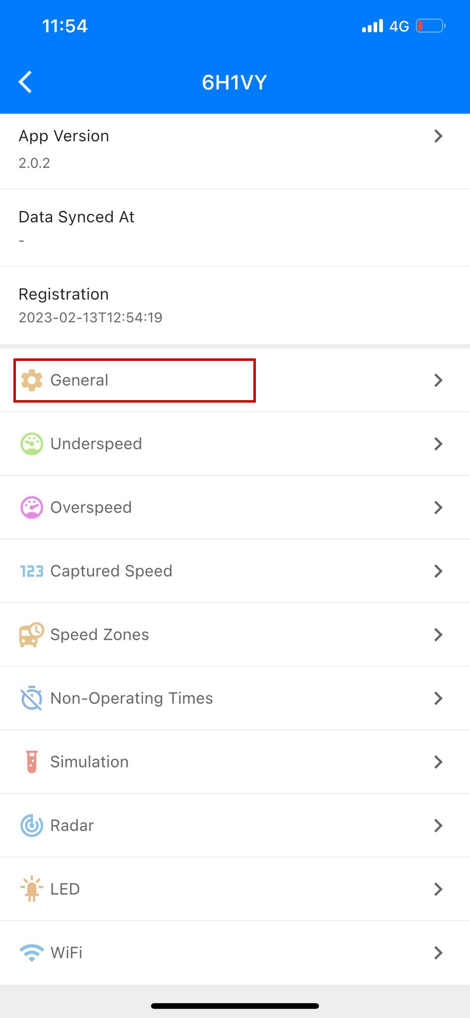
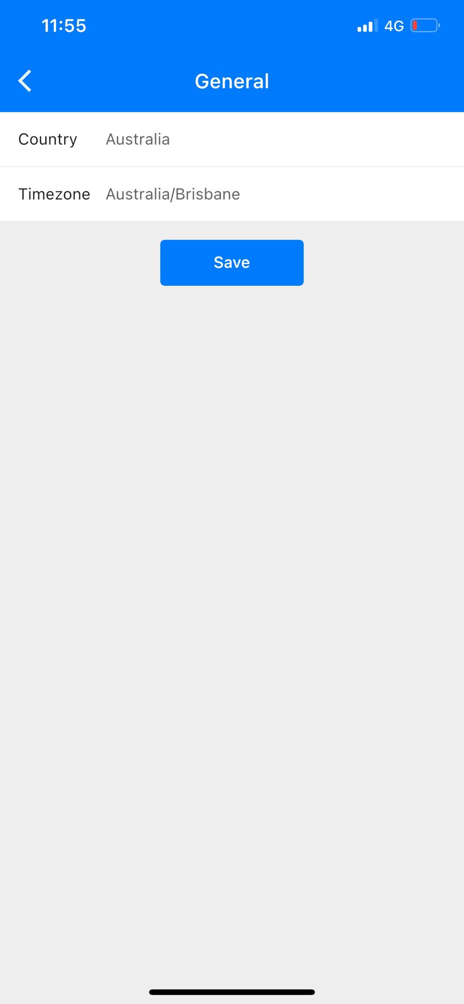
The “Time Zone” settings can be found under the main menu item “General”. To set your time zone, select your country, select your timezone, than press save.
STEP (9) – Configure Speed Zone
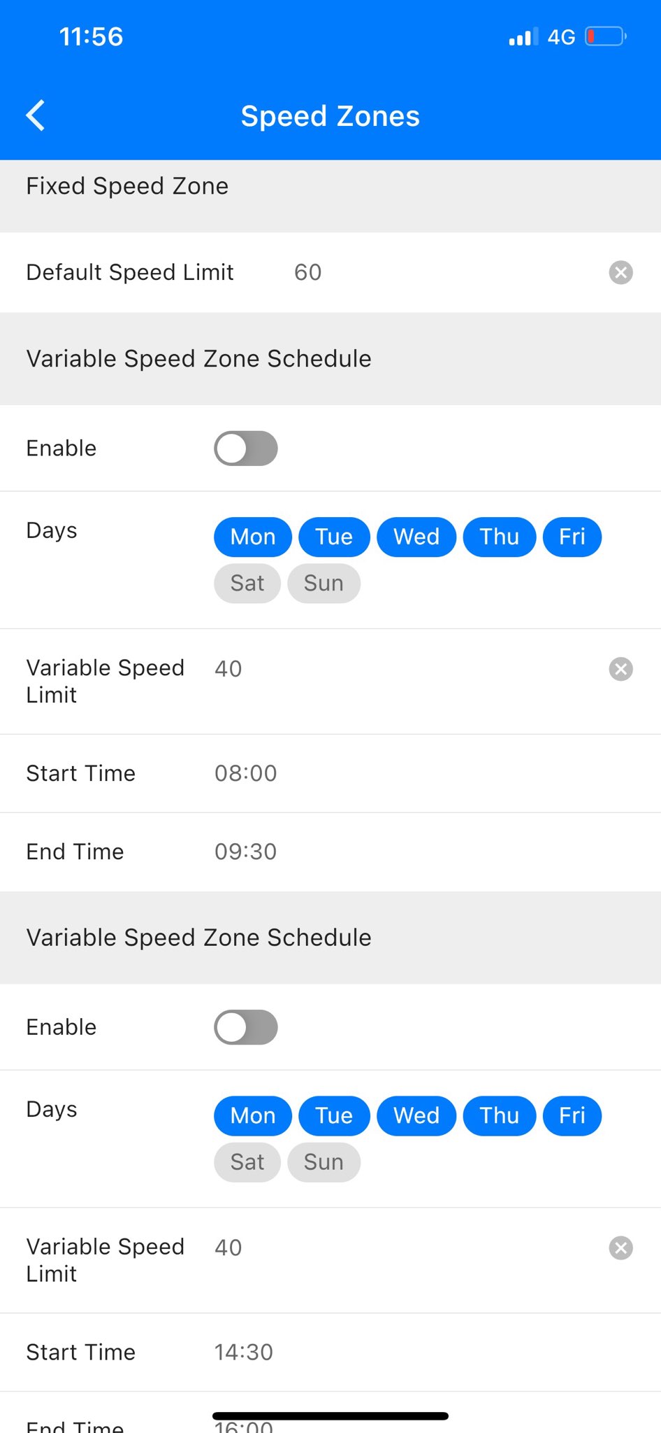
A unique feature not available in other Radar Speed Signs is the ability to add multiple speed zones. Example – Schools in Australia have multiple speed zones, 40klm between 7.30am to 9.00am and 2.30pm to 4pm, and 60klms outside these times during school days.
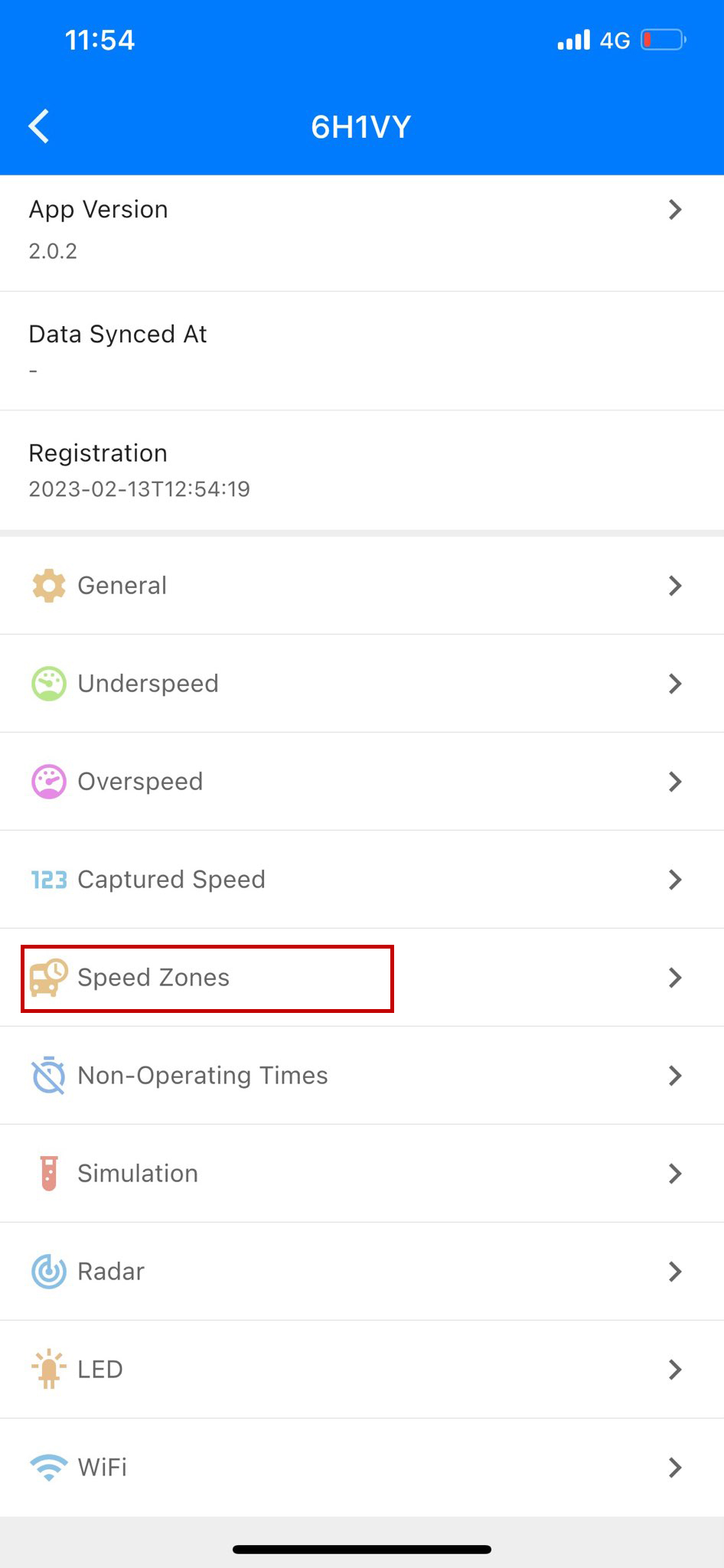
To configure the “Speed Zones”, click on “Speed Zones” located on the main menu. If you don’t need to use multiple speed zones, just add the deployment site speed limit at “Default Speed Limit” and press save. Vehicles travelling over the default speed limit will trigger the “Overspeed Message”, and vehicles travelling under the default speed limit will trigger the “Underspeed Message”.
To deploy the Radar Speed Sign in locations with multiple speed zones, simply “Enable” the “Variable Speed Zone Schedule” and set the “Variable Speed Limit”, the “Start Time”, “End Time”, and press save. For deployment in School Zones, non-operating times can be scheduled for School holidays, ensuring that the Radar Speed Sign automatically adjusts to regulatory speed limits without manual intervention.
STEP (10) – Configure Underspeed Message
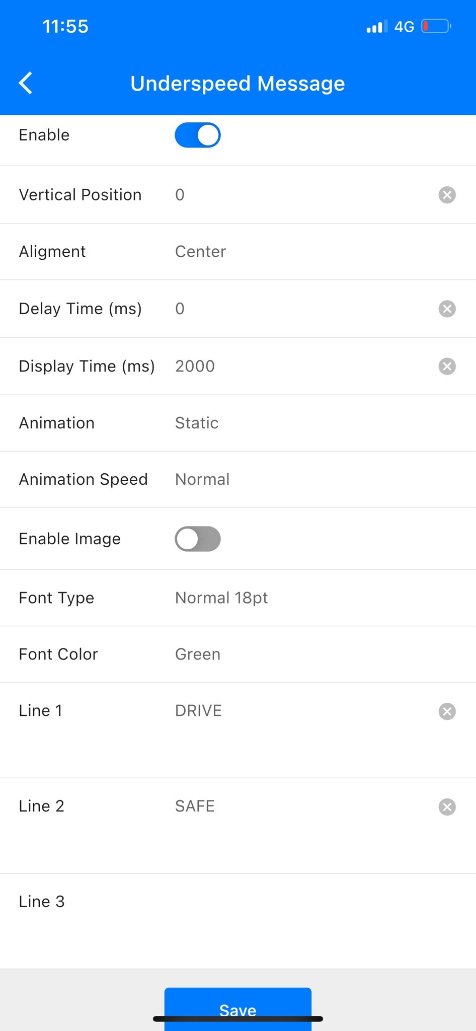
The underspeed message is seen by passing traffic when the Radar Speed Sign detects an approaching vehicle that is travelling under the speed limit. The displayed message can either be a custom text message, or display a green “Smiley Face”.
To setup, click on “Underspeed” from the main menu, than follow the prompts to either setup a custom “Text Message” or “Enable Image” to display the default green “Smiley Face”.
The “Delay Time” setting sets a time delay from when the vehicle is detected and when the “Underspeed Message” is displayed. This is generally set to zero.
The “Display TIme” is how long to display the “Underspeed Message” to the detected vehicle. Generally 2000ms is an ideal display time, but feel free to experiment with these settings to suit your deployment scenario.

STEP (11) – Configure Overspeed Message
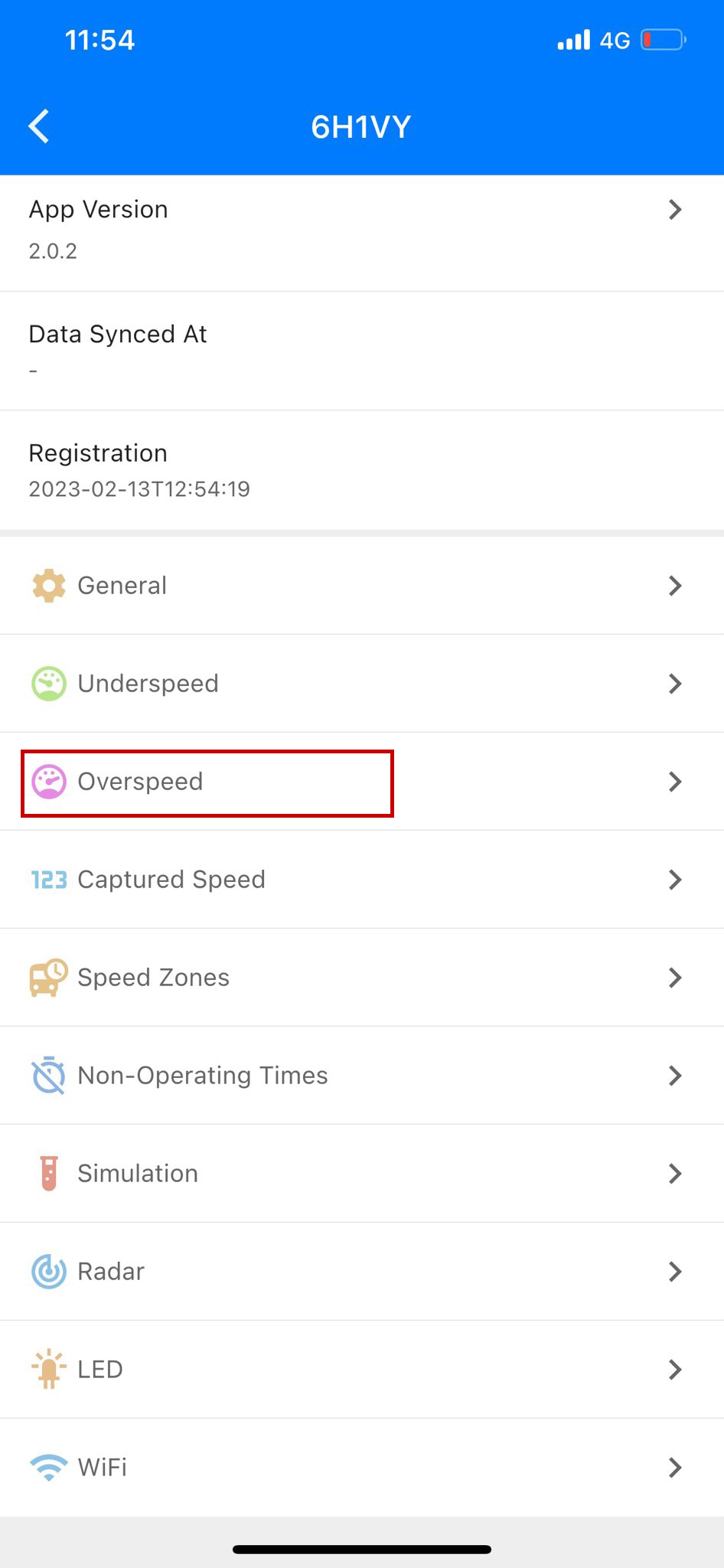
The “Overspeed Message” is seen by passing traffic when the Radar Speed Sign detects an approaching vehicle that is travelling over the speed limit. The displayed message can either be a custom text message, or display a red “Sad Face”.
To setup, click on “Overspeed” from the main menu, than follow the prompts to either setup a custom “Text Message” or “Enable Image” to display the default red “Sad Face”.
The “Delay Time” setting sets a time delay from when the vehicle is detected and when the “Overspeed Message” is displayed. This is generally set to zero.
The “Display TIme” is how long to display the “Overspeed Message” to the detected vehicle. Generally 2000ms is an ideal display time, but feel free to experiment with these settings to suit your deployment scenario.

STEP (12) – Configure Captured Speed
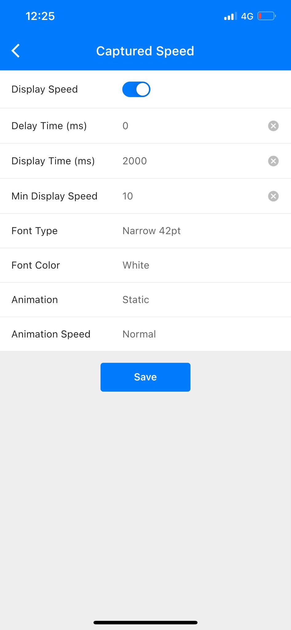
The “Captured Speed” is the detected approaching vehicles speed. When the Radar Speed Sign detects a vehicle. The first message displayed to the approaching vehicle is the captured speed, followed by either an “Overspeed” or “Underspeed” message.
The user can select to either “Enable” or “Disable” the display of the detected vehicles speed; while still allowing the “Underspeed” or “Overspeed” message of detected vehicles to be displayed.
This feature is often used at Road Work sites, warning drivers of roadworks ahead, and for overspeed vehicles, the “Overspeed Message” is triggered, displaying a warning message to vehicles.
Note that all changed settings need to be saved before taking effect on the Radar Speed Sign.

STEP (13) – Deployment
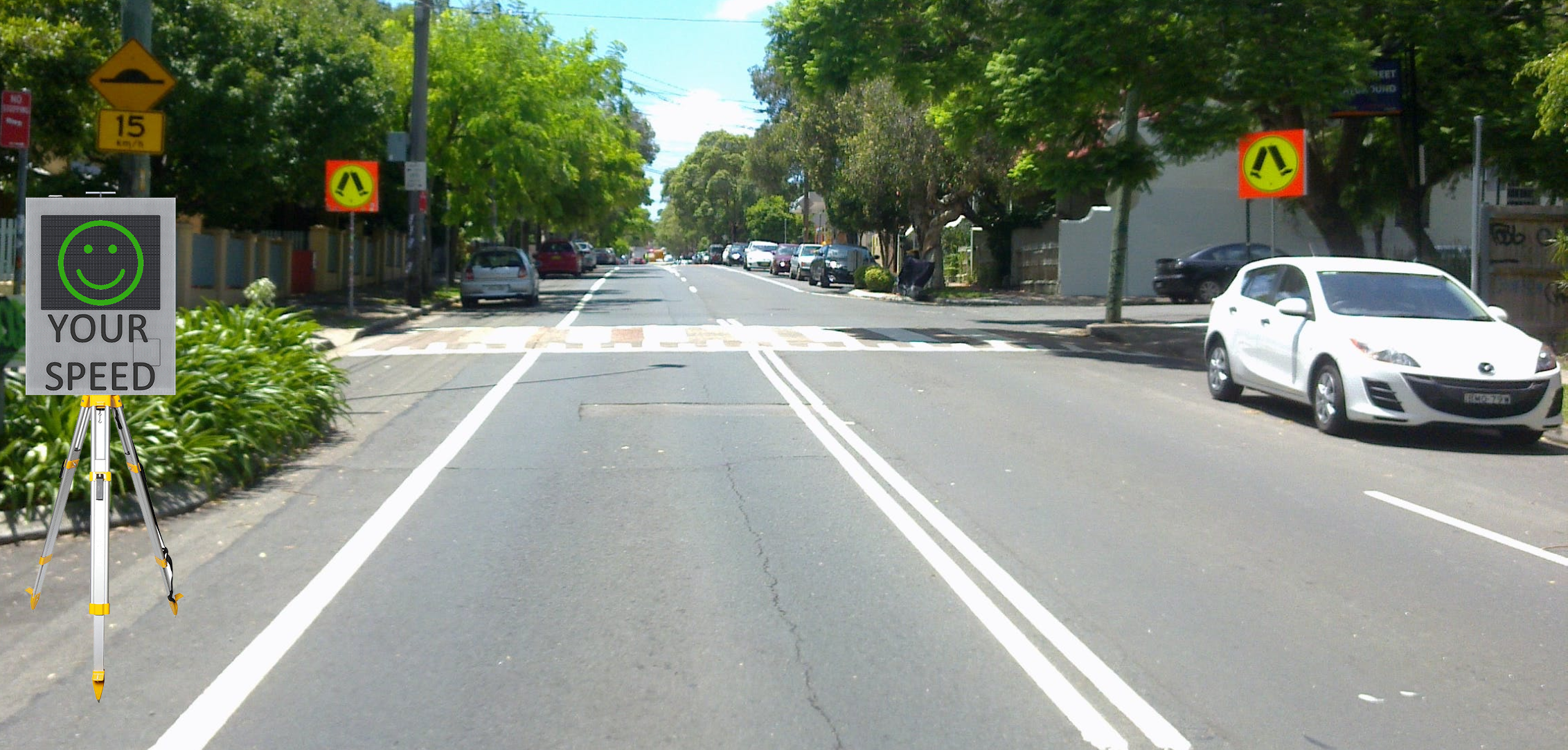
After completing the basic configuration settings from 1 to 12, the Radar Speed Sign is now ready for deployment. When deploying, ensure that the Radar Speed Sign is located as close to the side of the road as possible, with the front of the sign perpendicular to the oncoming traffic, this will ensure that the speed detection is accurate.
STEP (14) – Accessing Collected Traffic Data
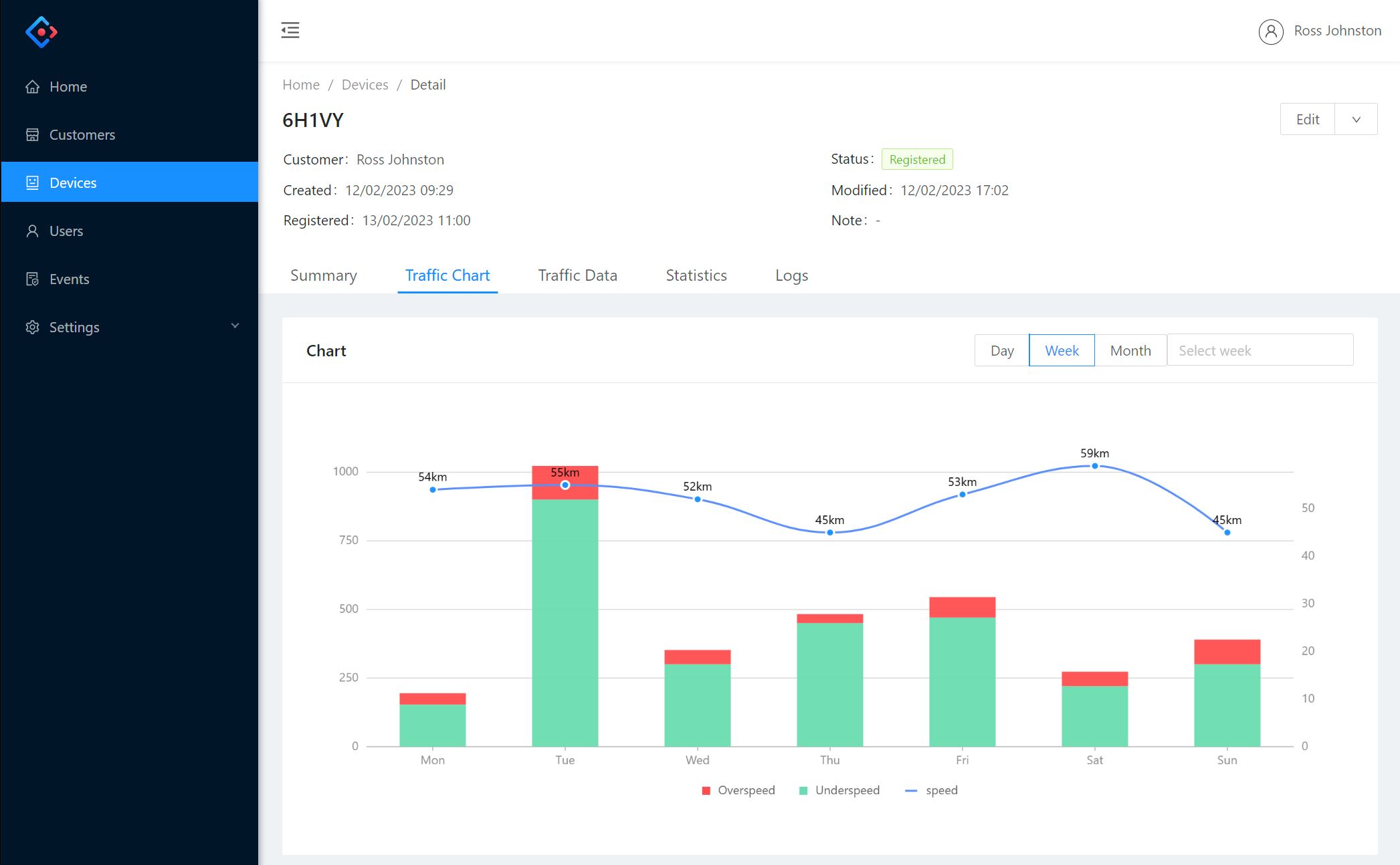
All data collected by the Radar Speed Sign is encrypted and uploaded to your Cloud CMS account every 9 mins, providing that the Radar Speed Sign is connected to a internet enabled WIFI connection.
To view the collected data, login to your Cloud CMS account, go to “Devices”, select the Radar Speed Sign from your list of devices, and click on the relevant data viewing tab to view the corresponding data.
ADVANCED CONFIGURATION GUIDE
The above User Guide is a simple startup guide to get your Radar Speed Sign powered-up and deployed. The “Advanced Configuration Guide” explains how to Setup “Non-Operating Times”, Setup the automatic brightness control for the “LED” screen, Test the operation of the Radar Speed Sign using the “Simulation” feature, check for hardware firmware updates, adding additional users, enabling “Two-Factor-Authentication”, and Cloud CMS features.